Inspired by Mr Chris Edward’s recent video putting together a GBS-8200 Amiga VGA “adapter” I thought I would take on the challenge and make one as cheaply as I could. The scart adapters available online are just so hit and miss with many of them only supporting composite inputs despite advertising RGB support. This has made ordering them from China (AliExppress) no longer viable.
This adapter would allow me to use the VGA input of my PC monitor for “testing” purposes and open up many more display possibilities without having to steal the OSSC from my 1200.
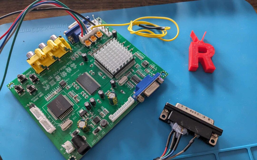
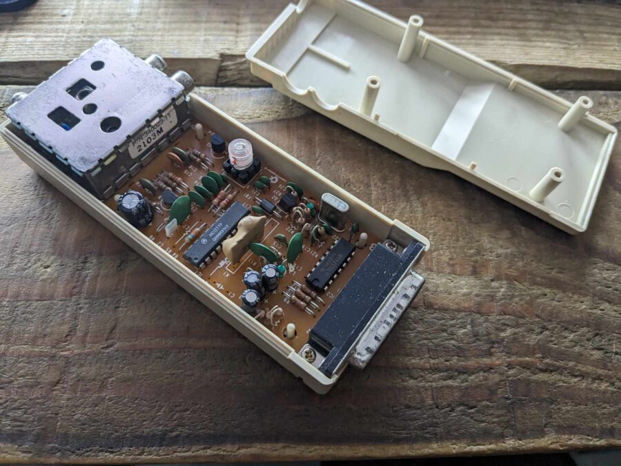
After laying down a measly £21.99 on Amazon the board arrived the next day. It didn’t include a power supply but I have an array of 5v adapters kicking about in the office. As well as the board I also needed a DB23 female socket for the project. Since I have at least 20 Amiga video modulators kicking about I decided to “repurpose” the useless brick and borrowed the connector. Before anyone gets excited – I took apart one modulator… I’ve lost count of how many I’ve simply thrown away.
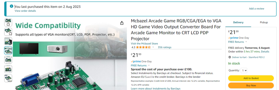
Product link here – https://amzn.to/3s06XYE
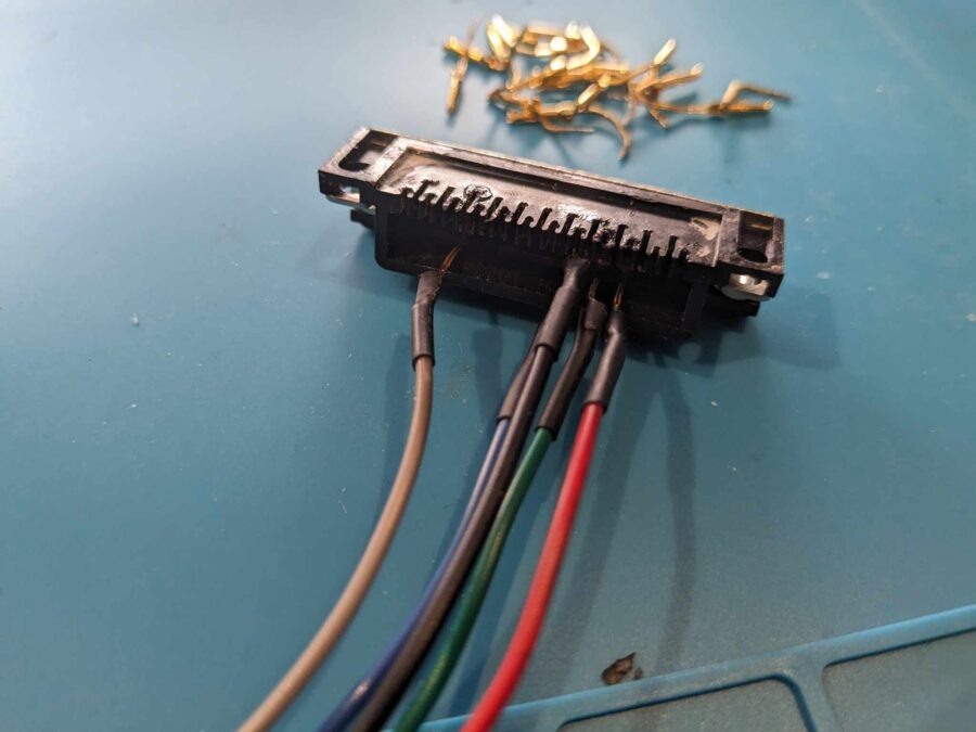
The connector was easily “snipped” away and desoldered.
The only real use for these!
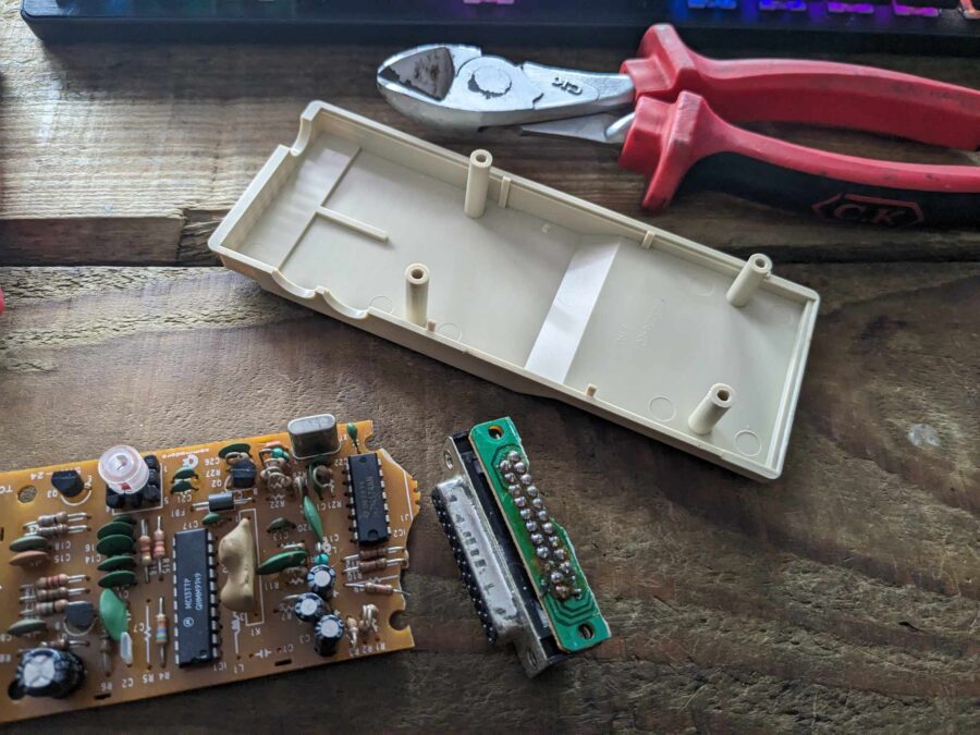
After all these years the connector was released with a satisfying crunch as the PCB just crumbed apart
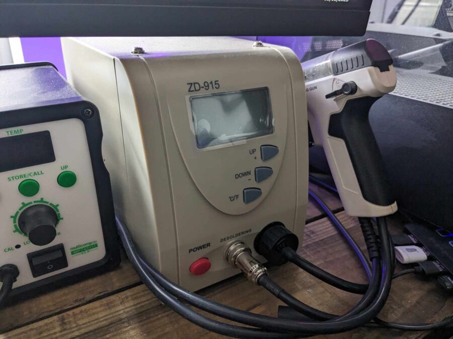
These are a godsend. It made easy work of getting the connector away from the PCB
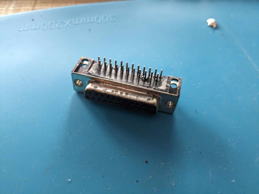
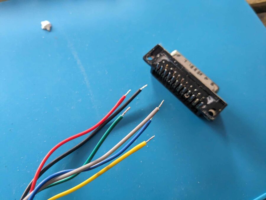
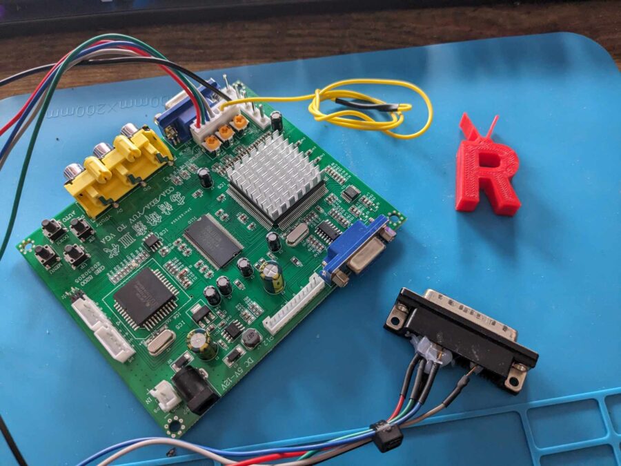
After cleaning up the pins the connector was ready to attach the GBS cables. The pins were treated to a little flix and tinned to make connecting the wires a breeze. It was connected as below
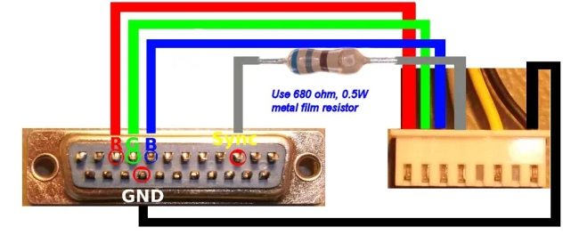
Image Credit – Ian Steadman https://ianstedman.wordpress.com/2015/01/25/gbs-82xx-experiments-part-2/
Pinout borrowed with thanks from https://ianstedman.wordpress.com/2015/01/25/gbs-82xx-experiments-part-2/. It’s well worth a read so check out the page.
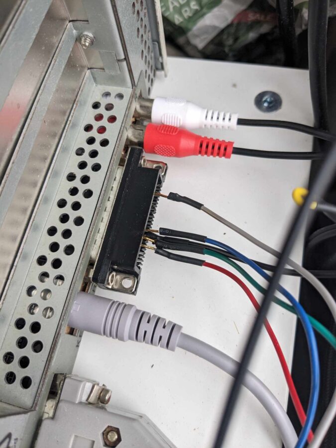
I also took the time to put some heat shrink around the cables.
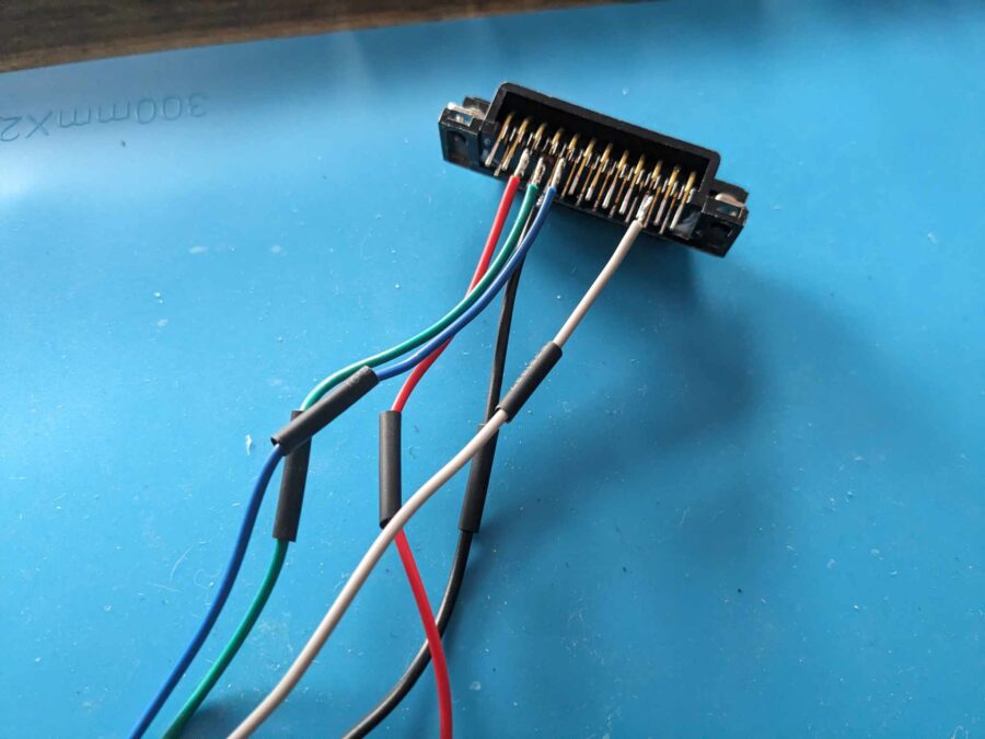
It turned out quite nice but I didn’t really think about how the connector was right-angled. This made things interesting in my initial testing.
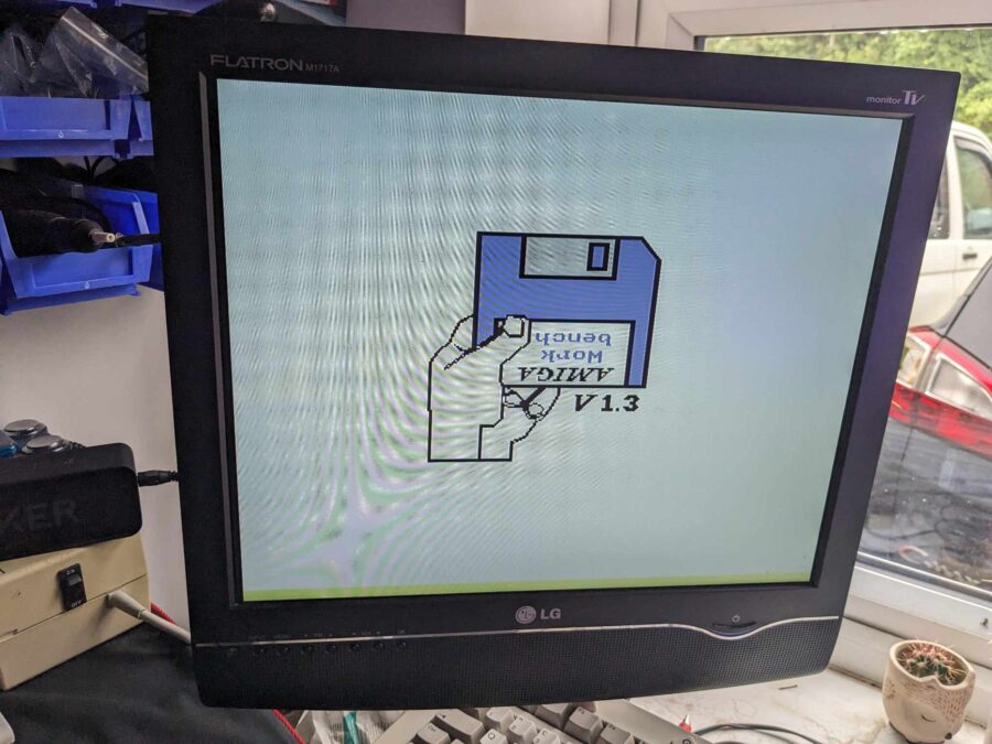
The 500 board was given a little lift above the desk for the first round of testing.
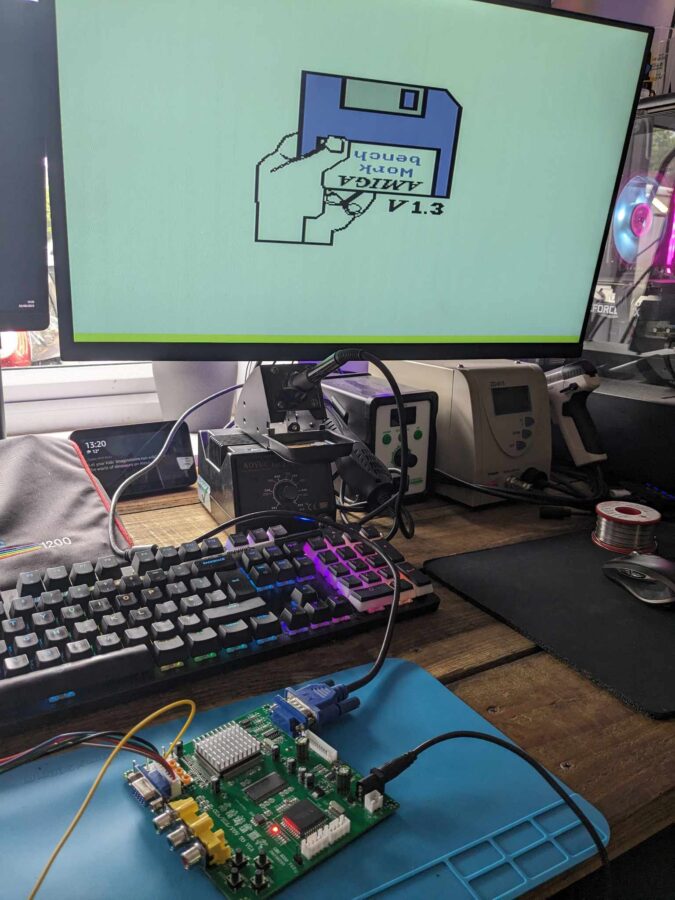
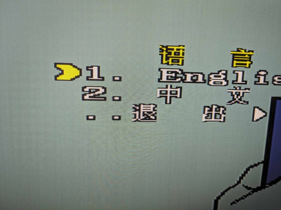
It only bloody worked first time however the menu system was in Chinese. To help change that press the menu button – select option 4. then English.
I’m not going to lie, whilst it worked on my 27″ LG panel it looked pretty trash. Luckily, I have a 15″ LG Flatron with VGA inputs which is great because it also supports 15Hz so it’s great to compare it against a normal scart signal.
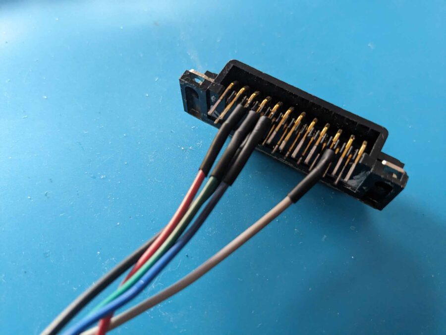
First up was to straighten the pins and remove the pins that aren’t required. In hindsight, I should have done this before wiring it up. Nevermind.
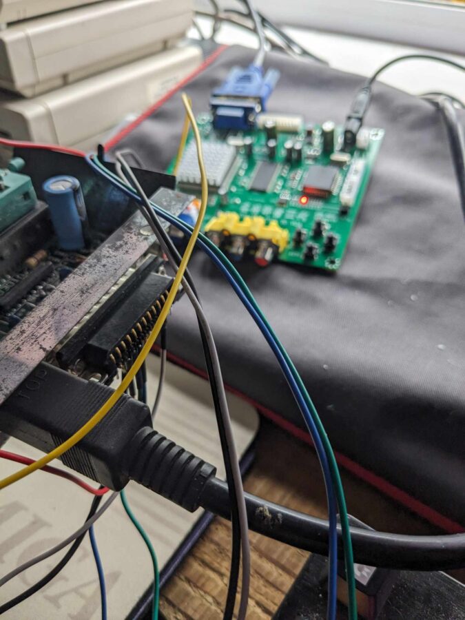
Now it was time for some testing. I connected it to my 4000 and popped in the VGA cable.
Wiring them after straightening the connectors would have stopped the chance of the bare cables touching. You live and learn I guess. Nothing a little hot glue wouldn’t fix.
The display needed a little tweaking through the menu. Just to get the colour balance and horizontal position right. Just have a play with it as I guess it will be different depending on the display you are using.
Results
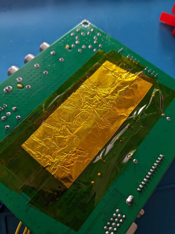
Overall, the results were pretty good. There is some pixel distortion and sparkling around the cursor. On a moving picture, you can’t really notice it but on Workbench it’s pretty apparent. From watching the RMC videos and reading other resources I understand that these issues could be down to interference. There are a number of things that can be done – I did the shielding “mod” but the issues were still there. I also need to add the resistor to the sync. I’ll visit that in the next part.
Display examples
Interference
A little Jesus on Es
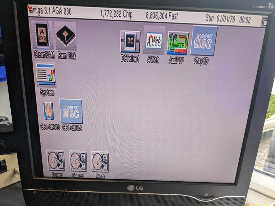
My 4000 desktop
First thoughts
Despite the issues, the GBS seems like a great solution. If I can just work out the interference problem it will be a great way of connecting the Amiga to a more modern display or even a way of utilising a VGA CRT. 15kHz LCDs are becoming harder to find so being about to output over 31Khz opens the door to many other options by increasing the scan rate and resolution. If you have any thoughts or ideas about the interference issues then please let me know in the comments below, contact me [email protected] or on social media.
I’ll be designing a little enclosure for the DB23 connector that’ll clean up the mess I made and also house the resistor (when it arrives). I’ll make the STL available for people to print at home.
Let’s hear from you!
Have you made one of these? Did you manage to fix the interference issues? Let me know in the comments below – it’ll help me for part 2!
Resources
- RMC Video – https://www.youtube.com/watch?v=q3J4QJsn0ig
- Chris Edwards Video – https://www.youtube.com/watch?v=sTI1_LA9XLM&t=197s
- Ian Stedman – https://ianstedman.wordpress.com/2015/01/25/gbs-82xx-experiments-part-2/
- Credit to Ian for the pin out shown above
Amazon Links
- GBS-8200 https://amzn.to/3OJwRsx
- OSSC https://amzn.to/3QslPcz
- Amiga Scart cable https://amzn.to/3s0UmVf
- Desolder Station https://amzn.to/3QqI9TE
Karl,
I don’t have the knowledge or skills, but I would be curious to know whether you could do something similar and use the signals from the Amiga video port to feed into the following to produce a HDMI singal?
https://zxbyte.ru/byte_connection_to_svga_monitors.htm#pico
You can get version with hdmi output does cost a bit more. But wire in just the same way.