Firstly, thanks for all the feedback and messages about our original RT-50B Mean Well build which covered the installation of the larger RT-50B into an original Amiga PSU case. It’s been great to see my guide used for preserving many original housings whilst safeguarding our glorious Commodore hardware.
Now it’s time for the equally as powerful but pocket-size RPT-60B power supply. Why is this I hear you ask? Firstly, stock shortages meant that I was unable to find a reliable supplier of the RT-50B and I wanted a new challenge.
Again I’ll cover this project in as much detail as possible to help you build your own. I’m open to making them if you don’t feel confident in doing so yourself, feel free to get in touch.
Be aware that some of the steps are reused from our previous project. I’d also like to thank Peter Mulholland for his wise words of wisdom and expert advice.
What’s the difference between the RPT-60B and RT-50B?
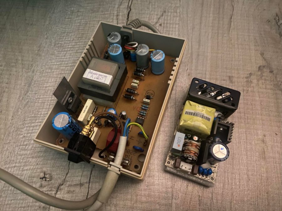
The most significant difference is the size. The RPT-60B is just 101.6mm x 50.8mm with a depth of 29mm whilst the RT-50B comes in at a whopping 99mm x 97mm with a depth of 36mm. The reduction in width makes a real difference in the power supplies, giving you much more room for activities. The saving in physical dimension reduces its weight by half, weighing in at just 150g vs 410g.
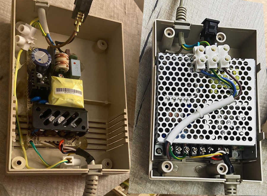
RTP-60B (left) vs RT-50B (right)
Power Output
Despite the 60 vs 50 in the model numbers, on paper, the two power supplies put out exactly the same amount (I expected 60W tbh). Let’s compare them in the table below
PSU |
RPT-60B |
RT-50B |
| 5v Amps | 4 Amp | 4 Amp |
| 12v Amps | 2.0 Amp | 2.0 Amp |
| -12v Amps | 0.5 Amp | 0.5 Amp |
| Output Power | 50w | 50w |
| Dimensions mm | 101.6 x 50.8 x 29 | 99 x 97 x 36 |
| Weight | 150g | 410g |
| Price * | £20.21 | £21.19 |
- Prices plus VAT from Mouser.co.uk – as of 12/1/23
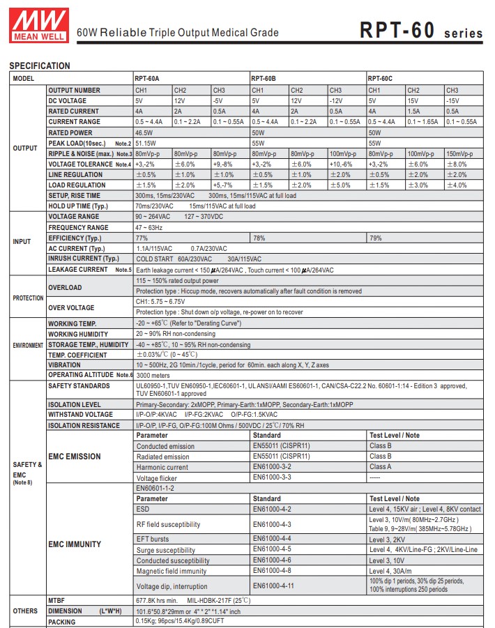
Here’s the fact sheet – check out the official Mean Well page if you need any “official” information – https://www.meanwell.co.uk/power-supplies/medical-grade-power-supplies/rpt-60-series
What does the original Amiga power supply output?
| PSU Type | Part number | +5V current | +12V current | -12V current | Combined Watt Power Rating |
| A500 type 1 | 312503-02 | 2.5 Amp | 1.0 Amp | 0.1 Amp | 25.7 Watts |
| A500 type 2 | 312503-03 | 4.5 Amp | 1.0 Amp | 0.1 Amp | 35.7 Watts |
| A6000 A1200 | 391029-02 | 3.0 Amp | 0.5 Amp | 0.1 Amp | 22.2 Watts |
| A600 A1200 | 391029-03 | 3.0 Amp | 0.5A | 0.1 Amp | 22.2 Watts |
Even with beefy hardware added to the A1200 (68060 and some hard drives), you’ll be lucky to see over 3 amps 5v and 0.08A 12v for a combined total of around 15 watts.
For reference, a stock Amiga 500 pulls around 2A (5v) 10W – Amiga 600 1.7A (5v) 8.5w and a stock A1200 1.4A (5v) 7w. So unless you really need the extra power the RPT-60B is more than enough for most Amiga hardware.
Where to buy
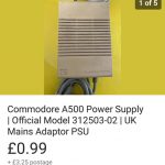
£1 plus postage?! Bargain!
If you’re looking for a spare Amiga PSU or don’t want to be without your current brick then I’d suggest heading over to eBay, You should be able to pick up a doner PSU for anything from a couple of quid up to around £25 for a working model.
For the power supply, I sourced mine from Mouser.co.uk – link here
What do you need?
Unlike the RT-50B installation, you’ll need a little more equipment to install this unit as you’ll need to desolder the power headers for safe fixing. You could make your own harness connect using the factory connectors but I opted to “hard wire” the cables in.
- Multimeter
- Soldering Iron
- Solder / Flux
- A small/medium Philips screwdriver
- Electrical block connections (optional)
- A Hot glue Gun
These are just examples of what you can buy on Amazon. I use an Aoyue 936 iron and some good-quality solder / flux.
Getting started
Firstly, ensure your PSU is not plugged into the main or Amiga, flip it over and remove the screws. You may need to use a thin screw driver down in the recessed holes. Once open CAREFULLY split open the PSU case.
WARNING! The power supply may still retain some electrical current. TREAT IT AS LIVE. Carefully snip all the wires to and from the power supply with insulated wire cutters then carefully remove the guts of the until using an insulated tool. I used the same wirecutters to grab onto one of the plates and lift it out. I can’t stress how careful enough how careful you should be.
Check the Pins
Using the multimeter’s continuity feature I traced and recorded power cable wires to the Amiga, recording them on the back of an Amazon packing envelope. Simply strip the ends of the wire and carefully test each pin and record the cable colour. We’ve seen lots of combinations of colours so DO NOT just go by the colours on some random Facebook post. This is why you need a multimeter
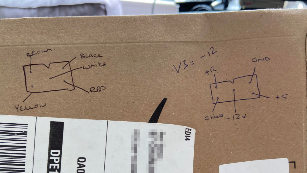
Recycling Amazon packages!
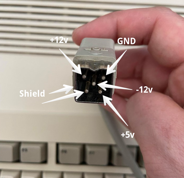
Amiga connector pins
To help you record your cables to pin colour use the following diagram.
Remove the Headers
Now remove the AC power connector header and 6-pin output header from the Mean Well PSU. I would recommend a little flux then heat each pin until the solder flows then push the pin down with the tip of the iron. Once all the pins are pushed down you should be able to carefully remove the headers with a pair of pliers. You could also use a hot air station but be sure to protect the other components/solder points with heat-resistant tape.
Once the pins are removed use some solder wick to clean up the contacts.
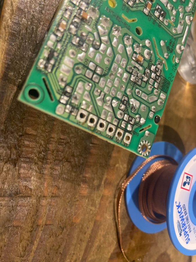
Cleaned and ready to go!
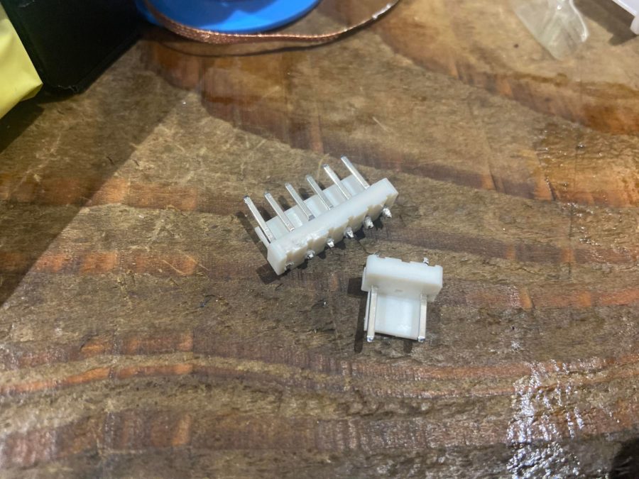
Connectors removed
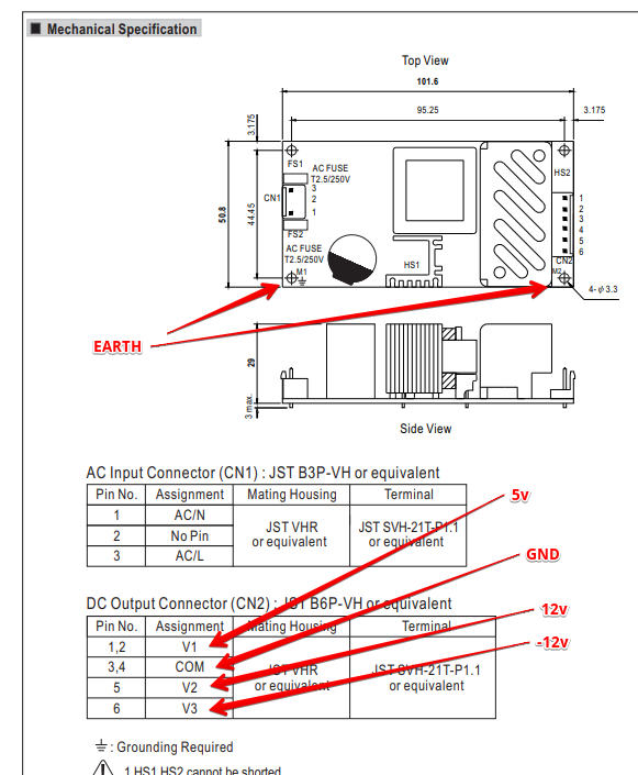
Wiring time!
With the connectors removed it’s time to start wiring things up.
See the table below. Note that you need to test your power connector cables on the Amiga end. These may differ. You have been warned.
Pin |
|
Colour |
| CN1 – 1 | NEUTRAL | BLUE |
| CN1 – 3 | LIVE | BROWN / BLACK |
| CN2 – 1 | 5V | RED |
| CN2 – 3 | GROUND | BLACK |
| CN2 – 5 | 12V | BROWN |
| CN2 -6 | -12V | WHITE |
| Earth / Shield | earth | Green / Yellow |
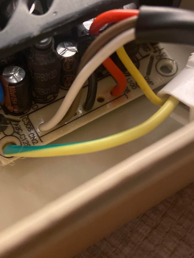
Note that CN1 is the AC input and CN2 is the DC to the Amiga. The PSU power switch cable is black / brown.
Note that the Earth from the AC side needs to connect both the Yellow connector on the Amiga cable and the earthing points on the PSU. I missed this on my first attempt (below) but you’ll see it in the finished photos below. The Earth should be connected to M1 & M2 (as per the diagram above).
It’s now time to solder everything up. Please please be careful. Make sure the AC cable is not connected to the mains. Safety first!
Use plenty of flux and be sure to clean up the connections once you are finished. As some of the connections are next to each other, use the multimeter continuity test feature to make sure they are not bridged.
You should also test continuity for all of the outputs on the CN2 connectors and make sure they are working on the pins as below. I tested continuity back from both shields all the way to the plug socket and the M1 / M2 connectors on the board.
Assembly!
With the PSU cabling ready let’s get it all together. I used hot glue to hold the PSU securely into the PSU housing. I had to remove it once to wire the earth on the board correctly and it was a mission to get out. Hot glue was a perfect solution for this, I would suggest applying it in each corner as the middle of the side just to make sure there is no chance of movement/
I also may look at making a 3D-printed mount in the future.
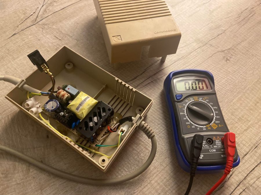
Testing the outputs
As with my previous Mean Well project, I took the opportunity to test the voltages on the output of the Amiga connector before connecting it to any of my beloved Amiga hardware. Be careful not to short any of the pins. Hold the black connector on the ground pin and check each of the other voltage pins. You should check the shield/earth pins back to the plug earth again. Please please be careful and get help from someone with steady hands if you need to.
Unlike the RT-50B the 5v does not have any adjustment. If it’s reading a little over 5V you’ll be fine.
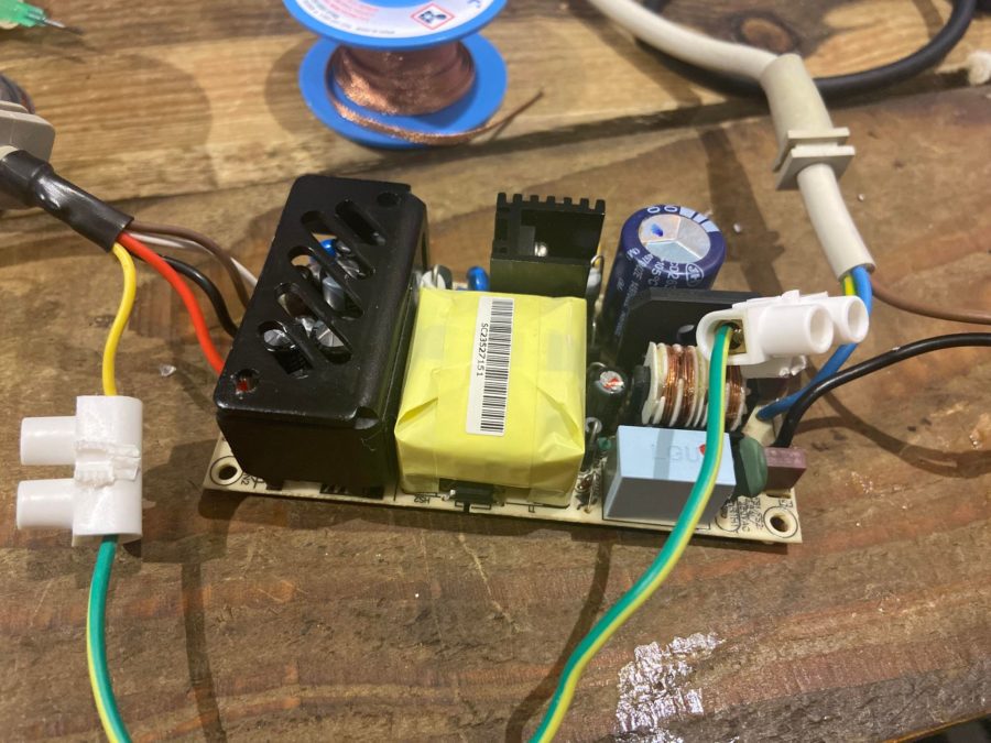
The final product
Shes done. An original tatty Amiga PSU with 30 years of “patina” and a brand new medical grade PSU. You beaut!
Final thoughts
Like the RT-50B, This whole project was a learning experience. Mistakes were made but I’m very happy with the outcome and I’m happy in the knowledge that both my Amiga setups can now benefit from a reliable power source.
For a very small outlay, it’s quite a feeling to know that I’ve managed to resurrect a piece of Amiga hardware that I would have normally disposed of in a heartbeat. I hope this projects offers an easy guide on how to make your own Retromodded PSU, for me it was a very rewarding project.
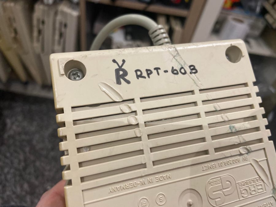
Note that as per the photo below, this PSU was a bit tatty, the melted parts you see were from a previous owner.
It’s official!
Let’s hear from you.
What do you think of my mini Amiga power supply project? Have I made any silly mistakes? How could this be improved? Do you prefer the RT-50B? Let us know in the comments below.
I found that the voltage drop by the time it reached the A600 circuit was fairly large, down to 4.8V or so.
The Mean Well RTP-60B has no 5v voltage adjust, BUT if you trace back from the 5v output on the underside of the board, there’s a transistor and an 0805 resistor to the bottom left. Parallel an 0805 resistor over the resistor already there and it raises the voltage slightly.
I used a 68K resistor and the voltage rose to about 5.2V and 5V inside the Amiga.
In witch orientation du you see the board when you say bottom left?
I’ve looked at where I think you mean and the resistor (R124) that’s on mine is marked 3161 so that indicates a resistance value of 3.16 kΩ, is that value different from your original, just wondering if perhaps they (meanwell) have already modified this.
I suppose I’ll find out when I assemble mine.