** Updated enclosure STL now available for download with wider and taller DB9 hole **
After ordering a custom joystick from Immortal Joysticks, I was in need of a way to use this legendary stick on the A500 mini. Rather than buy a solution, I opted to build one using my horrible soldering skills and drafted in one of my many 3D printers. As Amiga “builds” go, it’s a simple (and rewarding) project, perfect for someone who just likes to tinker.
Why?
I chose this solution due to its ease of construction, low latency and intuitive web interface, also thanks to Tim @ Team Pandory’s video (here). It also helps that they are very affordable.
Note: If you just want to use a joystick on another Amiga emulator then you may not need the button. This has been included to allow the launching of apps / LHA files from the A500 mini menu system.
If you don’t fancy making one yourself you can buy one from our shop. They take some time to build so they are made to order.
What do you need?
- 1 x 9 pin DB9 male connector – Amazon
- Assorted cables (I would suggest dupont cables) – Amazon
- 1 x Raspberry Pi Pico – Amazon
- Raspberry Pico Software – https://github.com/FeralAI/GP2040 – see below for details
- 1 x push button – Amazon
- Optional – a 3D printer, 2 x 8mm M3 screws
- Tools required: A soldering Iron, flux, a screw driver, sharp blade or deburring tool
As you can see from the part list, it comes to less than £30 and with all the spares you’ll have you can easily be made additional adapters by just buying more Raspberry Pi Picos. If you were to make 5 the cost would be around £10.50 each (plus the cost to make the enclosure). Bargain!
Soldering
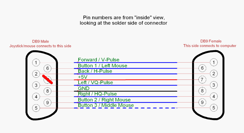
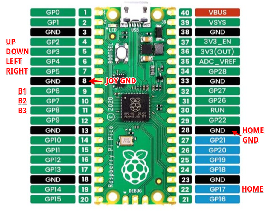
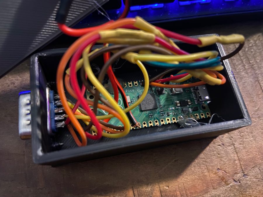
Time to wire up the DB9 connector to the Raspberry Pico. We wired ours up as below
DB9 male pin -> Pico GP pin
- 1 > GP2 (UP)
- 2 > GP3 (DOWN)
- 3 > GP5 (LEFT)
- 4 > GP4 (RIGHT)
- 5 > GP8 (BUTTON3)
- 6 > GP6 (BUTTON1)
- 7 – NOT USED (+5 v)
- 8 > GND (Any ground)
- 9 > GP7 (BUTTON2)
Button
- Red > GP17
- Black > GND (Any ground)
See the images below for further clarification
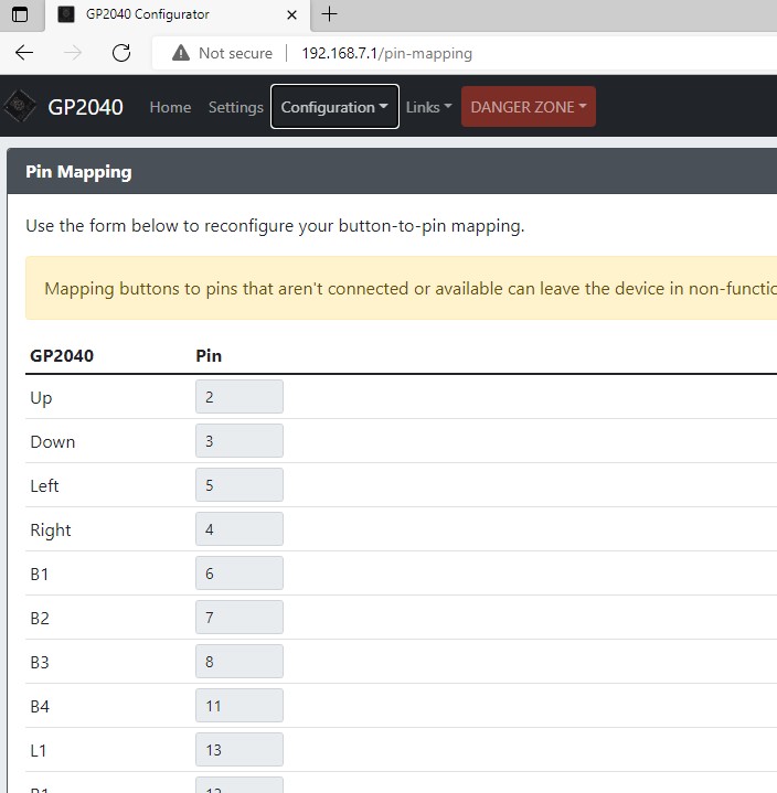
NOTE THE IMAGE BELOW IS INCORRECT (SWAP LEFT AND RIGHT) – you can change this in the software (as below)
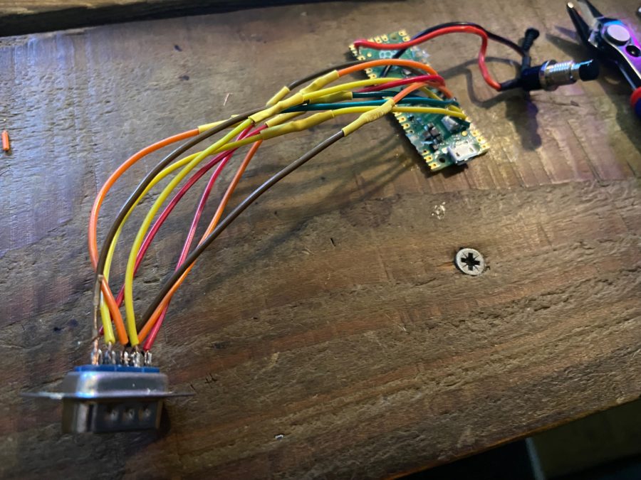
This is an example of how not to solder.
Program the Raspberry Pi Pico
Let’s install the software/firmware onto the Pico.
Navigate to https://github.com/FeralAI/GP2040 – go to Releases
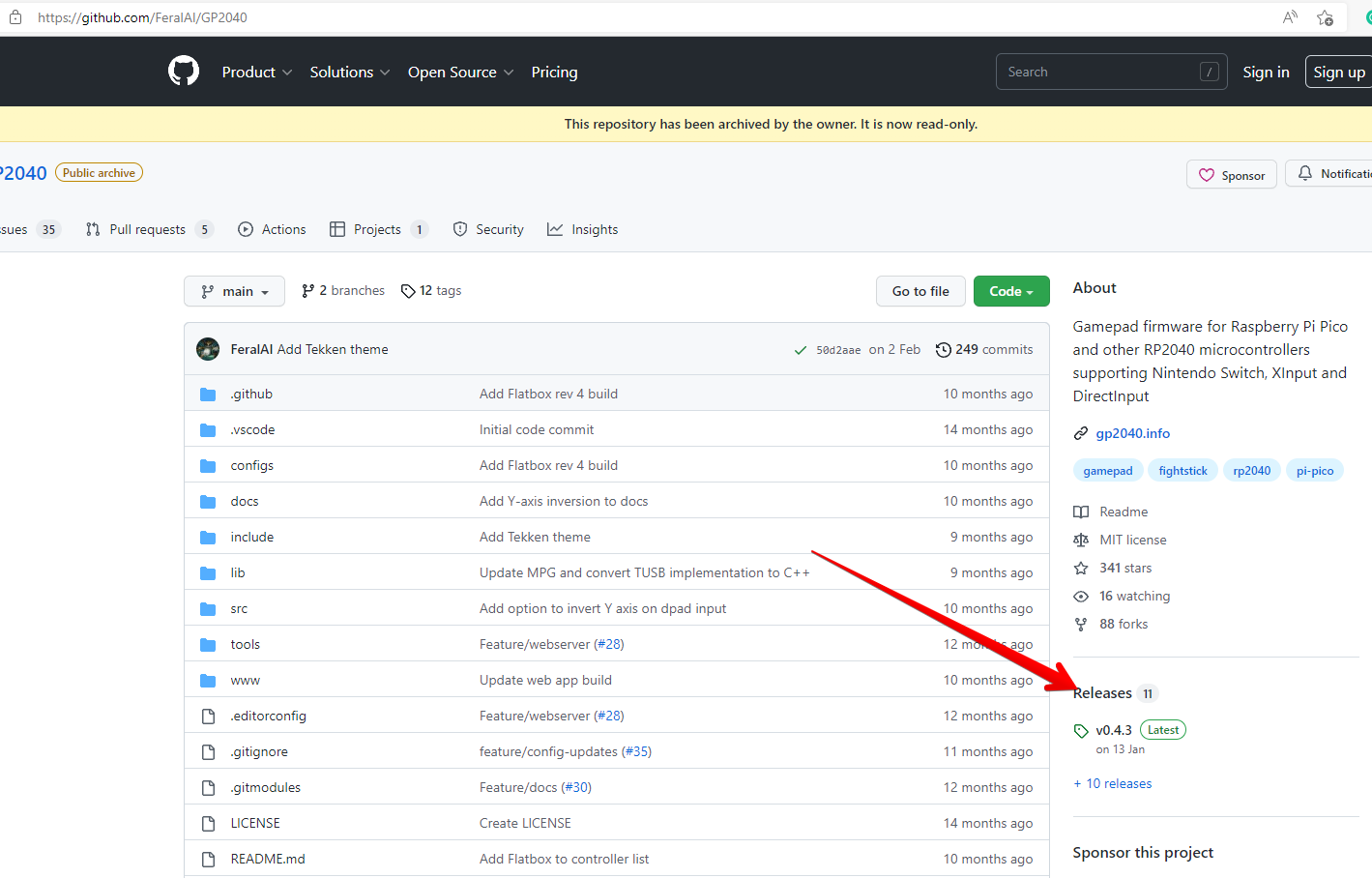
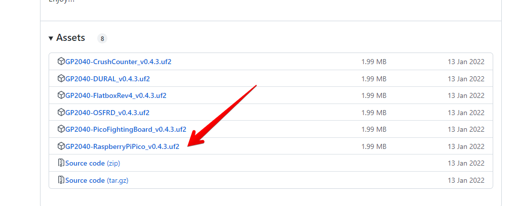
Scroll down to RaspberryPiPico and click to download
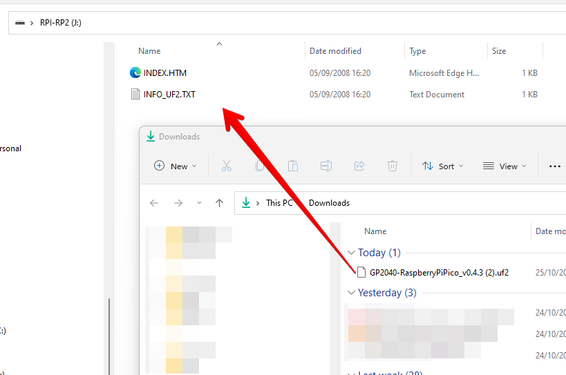
Connect the Raspberry Pi Pico using USB. This will open as a drive. Copy the downloaded uf2 file to the Pico
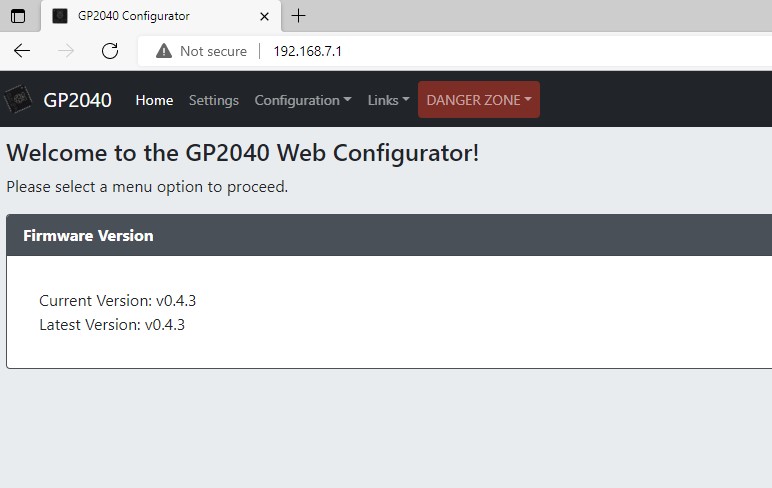
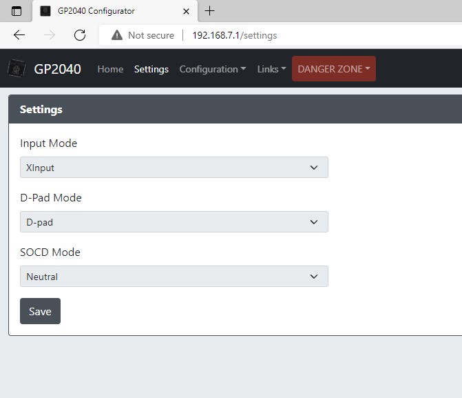
Now it’s time to change the board settings using the built in configuration web server. Unplug the Pico, press and hold the button you have soldered and plug the Pico back into the computer. Now navigate to http://192.168.7.1 – you will be greeted with the following webpage. Impressive!
Select Settings and change the Input Mode and other values as below
Under Configuration, you can customise the pin settings. This is very useful if you’ve made some changes to the pin connections.
With that completed. The board is now set up. We can now test that the inputs are working as expected.
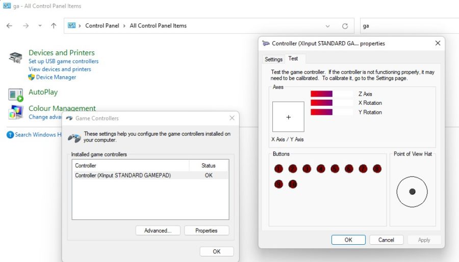
Testing in Windows
Open Control Panel > Navigate or search for Set up USB game controllers (open this) click Properties
You can now select the Text tab and check that the joystick is working as expected. Any issues with soldering / incorrect pins will highlight issues. If it’s not working as expected you can resolder your cables or edit the configuration in the web console as shown above.
If you’d like to contribute to this article with testing for other platforms then please get in touch.
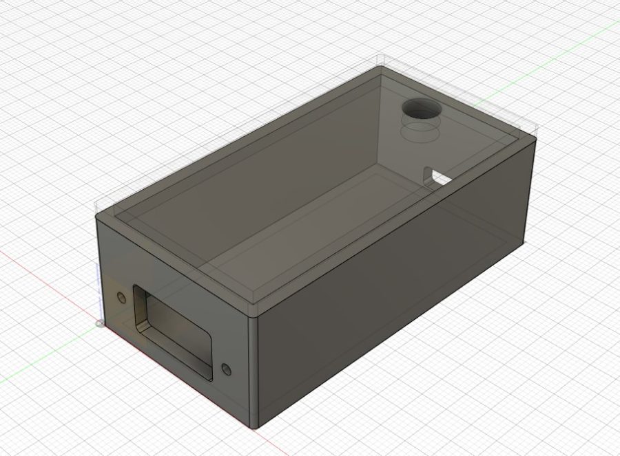
3D printed enclosure
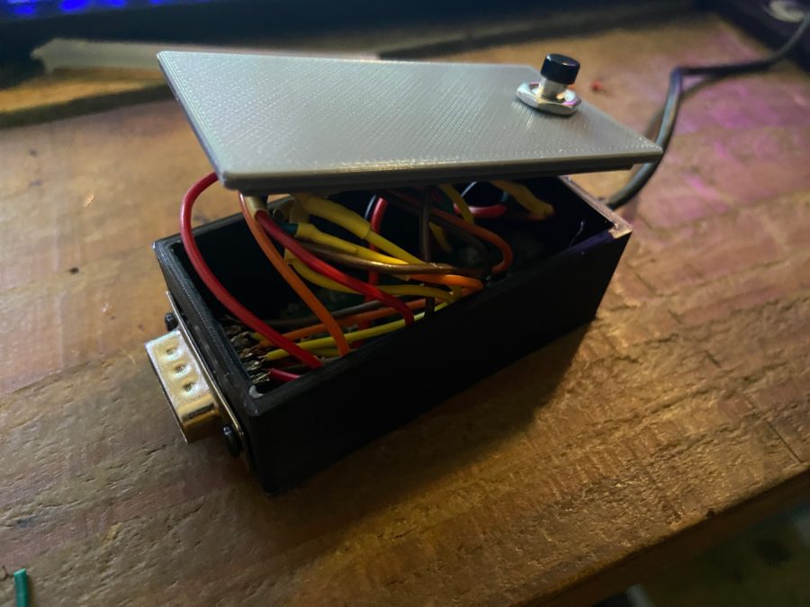
Rather than wrap this adapter up like a Mummy with electrical tape, I opted to design a small enclosure for the adapter in Fusion 360. This has been designed with the height of the Home button in mind.
Please feel free to download the STL files for the main body and lid below. Please note that I opted for a screwless lid which has been printed the same size as the top opening. Depending on your print settings you may need to trim a little from the lid / body to allow them to fit. I used a deburring tool to achieve this but you can use a knife. Just remember to take a little off at a time.
You may also need to trim / cut the corners of the DB9 opening to allow the Pico board to be inserted into the enclosure. A much better idea would be to have the board inside the enclosure before you solder so no cutting is required. In hindsight, I would have made longer cables and soldered it all in place.
Note that I have cut a circular hole in the top of the lid to accommodate the button. To keep the board secure I would recommend connecting the USB micro cable and hot glue the Pico board in place (example below).
** Update ** I’ve now added an STL for a lid without the hole to the download below
Use this one with a larger DB9 hole
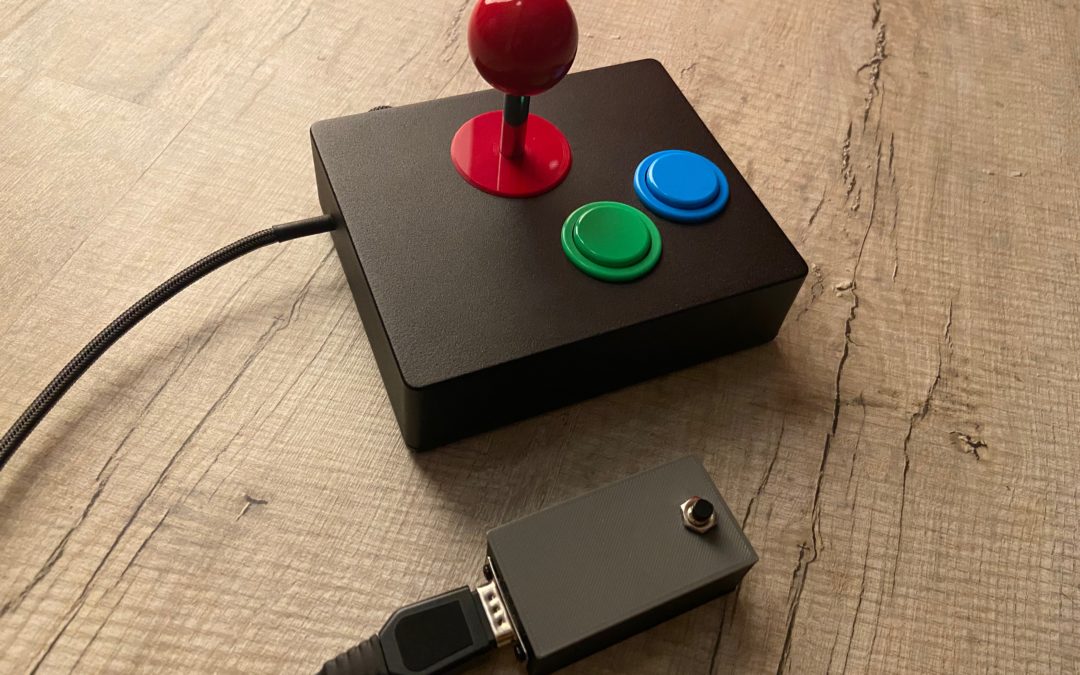
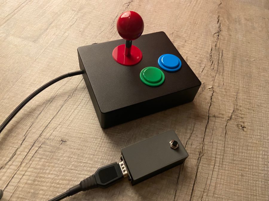
Finished!
And here it is. From the outside, it looks pretty damn good if I do say so myself. The inside and the soldering leaves a little to be desired but it works.
After ripping the wires away from the DB9 connector I had to extend the wires and resolder them as they were too short. I reused from cable offcuts for this. The joints are very small so be careful. If your soldering looks anything like then be very gentle or you risk breaking them or causing shorts.
Does it work?
Yes. Obviously. Whilst the A500 mini pad is great the Immortal Joystick is better in every way imanginable. It features a switchable / analog adjutsbale autofire and switchable fire to jump button.
https://www.immortaljoysticks.co.uk/ – This isn’t a sponsored article. I ordered my own stick – they are just bloody great.
And yes, you can use this with any other DB9 based Amiga controller.
Let’s hear from you!
Let us know if you have any suggestions or comments on this little project below. We’d love to see your adapters so please reach out to us using the contact page or via social media.
Credits
Full credit to the author of the GP4020 – you can see the acknowledgements and give a little back from the website – https://gp2040.info/#/?id=acknowledgements
The following website also contains documentation on GP2040 should you need it – https://gp2040.info/#/
Big thanks to Tim from Team Pandory for showcasing this project. Check out this YouTube Channel
hola q tal !!! por q no puedo entrar a la pagina web 192.168.7.1 ???
I built this, and it all works, even now in mid ’24. The 3D print is a bit of a tight fit, so I had to use a little persuasion to get screws and lid in place, but at least it is holding firm.
Thank you for this article :+1:
I found it difficult to get it working with the above software.
instead I used GP2000 ce, and that worked very good,- even on the amiga 500 mini.
More ekstra buttons could be in hand for the amiga 500 mini 😉