Our 2.4″ external Gotek displays have been very popular, so we’ve put together this guide to help you easily connect your 2.4″ Gotek OLED display.
For those unfamiliar with the Gotek Drive, let’s go through the basics.
What is a Gotek Drive
An Amiga Gotek drive is a USB floppy emulator that replaces the traditional floppy disk drive in Amiga computers. Instead of relying on aging floppy disks, the Gotek drive allows users to store and load software using a USB flash drive. It works by using ADF (Amiga Disk File) images, which are digital backups of original Amiga floppy disks. This makes it a convenient solution for preserving and accessing classic Amiga games, demos, and applications without the hassle of physical media. The Gotek drive was originally designed for other systems, such as sewing machines and music sequencers, but has since been adapted for retro computing.
To use a Gotek drive with an Amiga, it must be flashed with compatible firmware, such as FlashFloppy or HxC, which enables the Amiga to recognize it as a functional floppy drive. Some Gotek drives come with additional features, like an OLED display, a rotary selector, or even a buzzer that mimics the sound of a real floppy drive. Installation involves replacing the internal floppy drive or using an external enclosure, depending on the Amiga model. With a Gotek drive, Amiga enthusiasts can enjoy a vast library of software while preserving their hardware for years to come.
How to Program a Gotek Drive
We covered this in the article below
How to install your 2.4″ Gotek External Screen
Parts
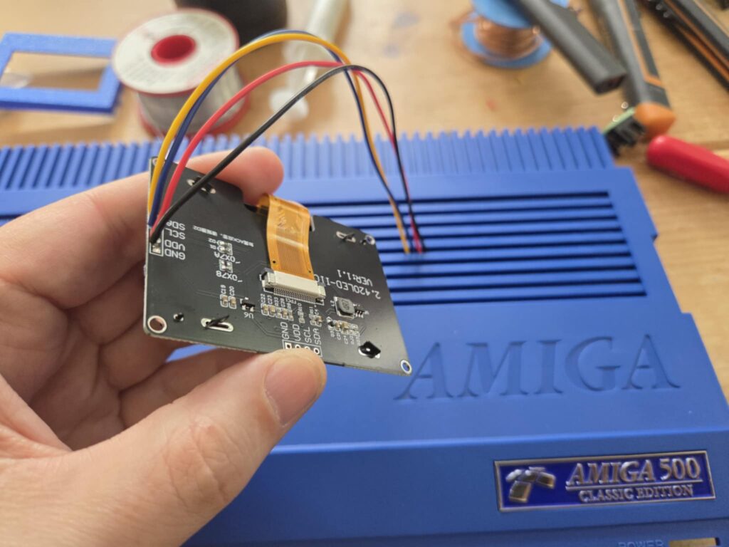
First, you’ll need our 2.4″ OLED display and surround, available from our store.
You’ll also need a 4-pin display connection cable. Alternatively, you can solder the display wires directly to the board. You will also need wires to connect the display, note that they will need to be thin enough to slide through the case vents.
Display Wiring
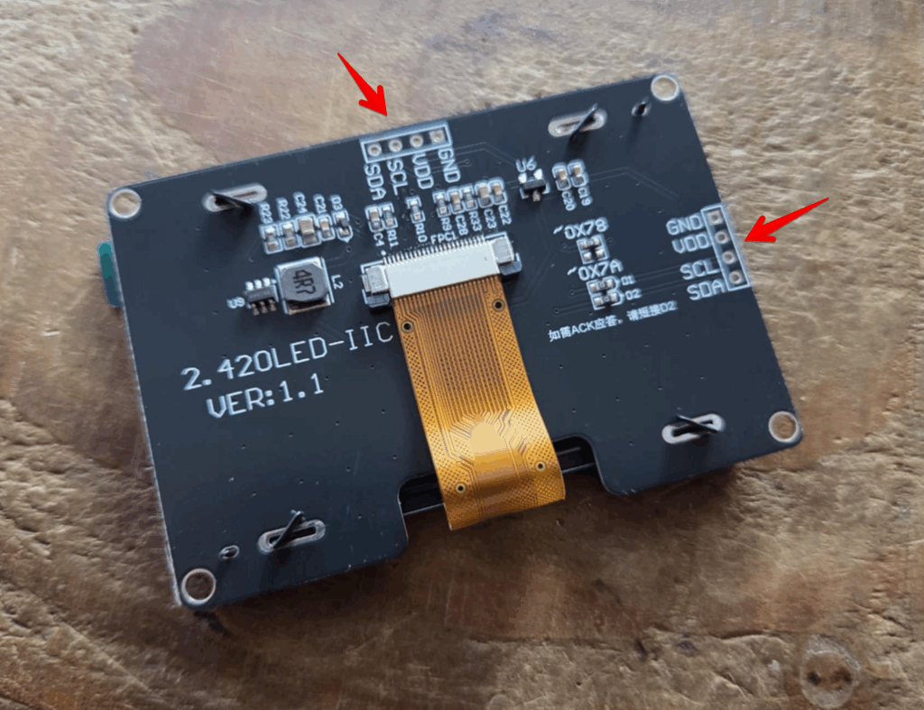
The 2.4″ OLED displays have header connections on both the top and left sides of the display. We suggest using the side headers.
Gotek Wiring
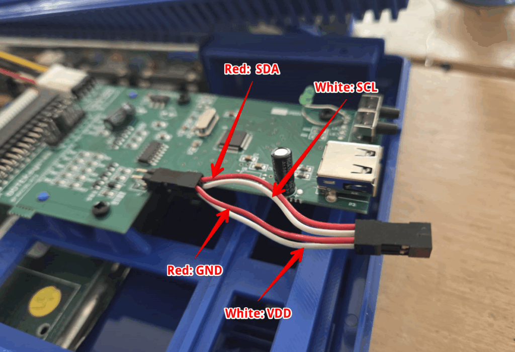
The Gotek wiring corresponds to the display header (J7) as shown below:
Pins (as you look towards the pins)
1 | 3
2 | 4
| Pin | Display |
|---|---|
| 1 | GND |
| 2 | VDD |
| 3 | SDA |
| 4 | SCL |
Routing the Cables
We routed the cables through the fifth vent, as shown below. Since the connectors cannot be fitted before feeding the cables, we opted to use Dupont cables to allow easy case removal. This means you must carefully solder the cables after they are threaded through the case. Just make sure to protect the case during this process.
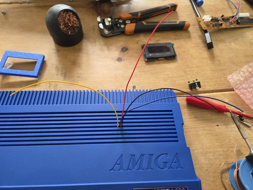
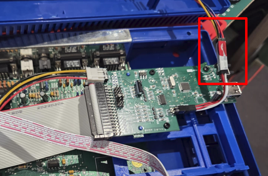
We secured the male Dupont connectors to the female ones with a little tape for added security.
Once the wiring is complete, simply push the display into the housing and adjust its positioning.
Note: If you’re using an case (as in this build), you may need to shave the locating pegs on the display housing down slightly. The vents are a little narrower than those on an original case.
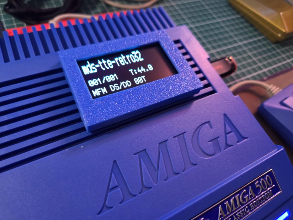
Screen config
With the display installed, the last step is to add the FF.cfg file. This file contains the configuration for the Gotek and, most importantly, the screen settings. We have opted for a three-line display with the top line slightly larger.
Download the zip file below and extract the FF.cfg file to the root of your USB stick.
The key lines in the configuration file are:
display-type = oled-128x64

oled-font = 6x13

display-order = 0d,1,2
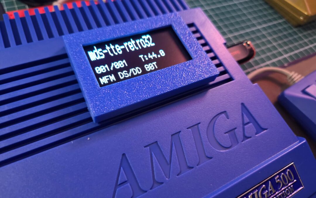
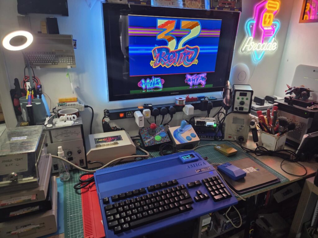
The final result!
Hopefully, you now have a beautiful 2.4″ Gotek display! Feel free to send us a photo of your setup at [email protected], and we’ll add it to our website.
External References
- Flashfloppy Hardware Mods : https://github.com/keirf/flashfloppy/wiki/Hardware-Mods
- Flashfloppy Github: https://github.com/keirf/flashfloppy
Thanks to Keir Fraser for all his amazing work on the Flashfloppy project
I notice that the 3d printed holder for the Gotek circuit board in this article looks a little different than the one you are selling in the shop, I presume since you don’t need a window for the small LCD screen. Do you have the files or do you sell this different holder? Thanks
Hi Jack
I simply just removed that part of the mount in the Bambu Lab slicer. It saves printing it.
I’ll add a listing up for one without the screen – I can also make one with the board moved into the middle so it has more room.
Hi i have got a new black a500 case and am fitting an internal gotek that comes with a break out box for display… the whole thing is already assembled.. What id like to know is how to get those wires through the top case vent to the breakout display box…
If the wires didnt have the small black connectors on it would be easier… How do i get the connectors off to reattach or even cut them off and buy new ones but dont know where to find them? or cut the cables and reattach with some kind of male and female connector